


No.188 Doubu Avenue, Hannan District, 430090 Wuhan, China


Views: 0 Author: Site Editor Publish Time: 2026-09-15 Origin: Site


Facility managers and contractors face a strict logistical bottleneck when executing high-reach maintenance or construction inside multi-story facilities. Crane access is impossible. Scaffolding disrupts daily operations and takes too long to build. You need high working heights for atriums and vaulted ceilings, but you must navigate standard doorways and freight elevators to get there. Can a compact spider lift fit in a freight elevator? Yes, it can. You just need to match the machine's physical constraints with the building's structural limits. We evaluate stowed dimensions, elevator weight classifications, floor loading limits, and power source requirements. This guide breaks down exactly how to measure, plan, and execute indoor transport safely without damaging the building infrastructure or the equipment.
Dimensional Viability: Many models are specifically engineered to collapse down to 31–35 inches in width, allowing them to pass through standard double doors and standard freight elevator doors.
Weight and Capacity Limits: Fitting physically is only half the equation; the lift's operating weight must strictly align with the freight elevator’s rated capacity (Class A, B, or C) to prevent catastrophic mechanical failure.
Point Loading Realities: The concentrated weight of a tracked machine requires careful calculation of floor loading limits, both in the elevator cab and the surrounding lobbies.
Emissions Compliance: Indoor transport necessitates zero-emission capabilities, making dual-power or battery-operated models mandatory for enclosed elevator transport.
The engineering behind these machines focuses entirely on maximizing vertical reach while minimizing the stowed footprint. To fit inside a standard freight elevator, the machine undergoes a radical physical transformation. The specific mechanical articulation allows the lift to shrink its footprint significantly. The front and rear outrigger legs swing inward toward the center chassis. Once aligned, hydraulic cylinders fold these legs upward into a vertical storage configuration. This eliminates the wide stance required during boom operation.
Track retraction mechanisms further reduce the overall width. Operators use hydraulic controls to pull the track frames inward along sliding steel axles. This function narrows the machine down to navigate tight elevator doors and confined corridors. When the tracks retract, micro-switches engage to tell the onboard computer the machine is in transport mode, which automatically disables the boom functions for safety.
Working Height Class | Typical Stowed Width | Typical Stowed Height | Typical Stowed Length (Basket Removed) |
|---|---|---|---|
40 - 50 Feet | 31 inches | 75 inches | 12 - 14 feet |
55 - 65 Feet | 35 inches | 78 inches | 14 - 16 feet |
70 - 85 Feet | 35 - 39 inches | 79 inches | 16 - 18 feet |
Navigating a heavy machine through a finished lobby and into an elevator requires extreme precision. A tracked spider lift utilizes a dual-track drive system that provides zero-turn capabilities. By driving one track forward and the other in reverse, the machine counter-rotates and pivots 360 degrees within its own footprint. This maneuverability facilitates precise alignment with elevator doors in confined lobbies where turning radii are severely restricted.
Loading a machine into an elevator cab presents significant pinch-point hazards. Operators cannot safely stand beside or behind the machine while driving it into a steel box. Remote-control operation becomes an absolute necessity. Tethered belly-box controls or wireless radio remotes allow the operator to stand outside the elevator cab. You monitor the track alignment and overhead clearances from a safe vantage point in the lobby. This eliminates the risk of an operator being crushed between the machine chassis and the elevator walls during the loading sequence.
You must outline critical measurements before attempting transport. Do not rely on architectural floor plans; measure the physical space yourself. Building settling, renovations, and added fixtures often change the actual clear space.
Measure the exact elevator door width at the narrowest point, checking for protruding door sensors or bumpers.
Measure the door height, ensuring the door header does not hang lower than the cab ceiling.
Measure the internal cab depth from the back wall to the closed door. Account for rear handrails, which often protrude 2 to 3 inches into the usable space.
Measure the ceiling height, paying close attention to recessed lighting, security cameras, or emergency escape hatches.
Address the risks of diagonal loading. If the machine is longer than the cab depth, you might try to load it diagonally. This geometry drastically reduces the available width, shifts the center of gravity, and creates severe pinch points against the cab walls. You must calculate the necessary clearances for the lift's basket. In almost all elevator transport scenarios, you must detach the basket prior to loading. Removing the basket shortens the overall length of the machine by two to three feet, making a straight-on approach viable.
Understanding freight elevator classifications dictates whether equipment transport is safe or catastrophic. Freight elevators fall into distinct categories based on structural engineering and intended use.
Class A (General Freight): The load is distributed manually or by hand trucks. The weight of any single piece of freight cannot exceed one-quarter of the elevator's rated capacity.
Class B (Motor Vehicle): Designed specifically for carrying automobiles. The structural frame supports the distributed weight of four tires.
Class C (Industrial Truck Loading): Designed for heavy, concentrated loads. Class C1 allows a forklift to drive into the cab with the load. Class C2 allows the forklift to load the cab but not ride in it. Class C3 allows heavy concentrated loads but no forklift.
You must understand the difference between static load capacity and rolling load capacity. Static capacity refers to the maximum weight the elevator can hold while stationary. Rolling load capacity accounts for the dynamic forces exerted when driving a heavy machine across the elevator threshold. A machine might weigh 4,000 pounds, sitting below a 5,000-pound static limit. However, driving that machine over the threshold exerts concentrated rolling loads that can shear the elevator floor supports if the cab lacks a Class C industrial rating.
The tracks of a narrow access spider lift concentrate thousands of pounds of machine weight into a very small surface area. You must calculate the point load pressure exerted by the machine. Divide the machine's total operating weight by the total surface area of the tracks in contact with the floor. For example, a 4,000-pound machine with 1,000 square inches of track contact area exerts 4 pounds per square inch (PSI) on the floor.
Elevator cab floors are often constructed of steel plating over a structural frame, but older or passenger-rated cabs may use wood or composite materials. The structural integrity of the elevator cab floor must exceed the machine's point load pressure. If the floor rating is insufficient, you must use load-distribution plates. Laying down steel road plates or heavy-duty 3/4-inch CDX plywood across the elevator floor spreads the track weight over a larger surface area. This prevents the tracks from punching through the cab floor during transport.
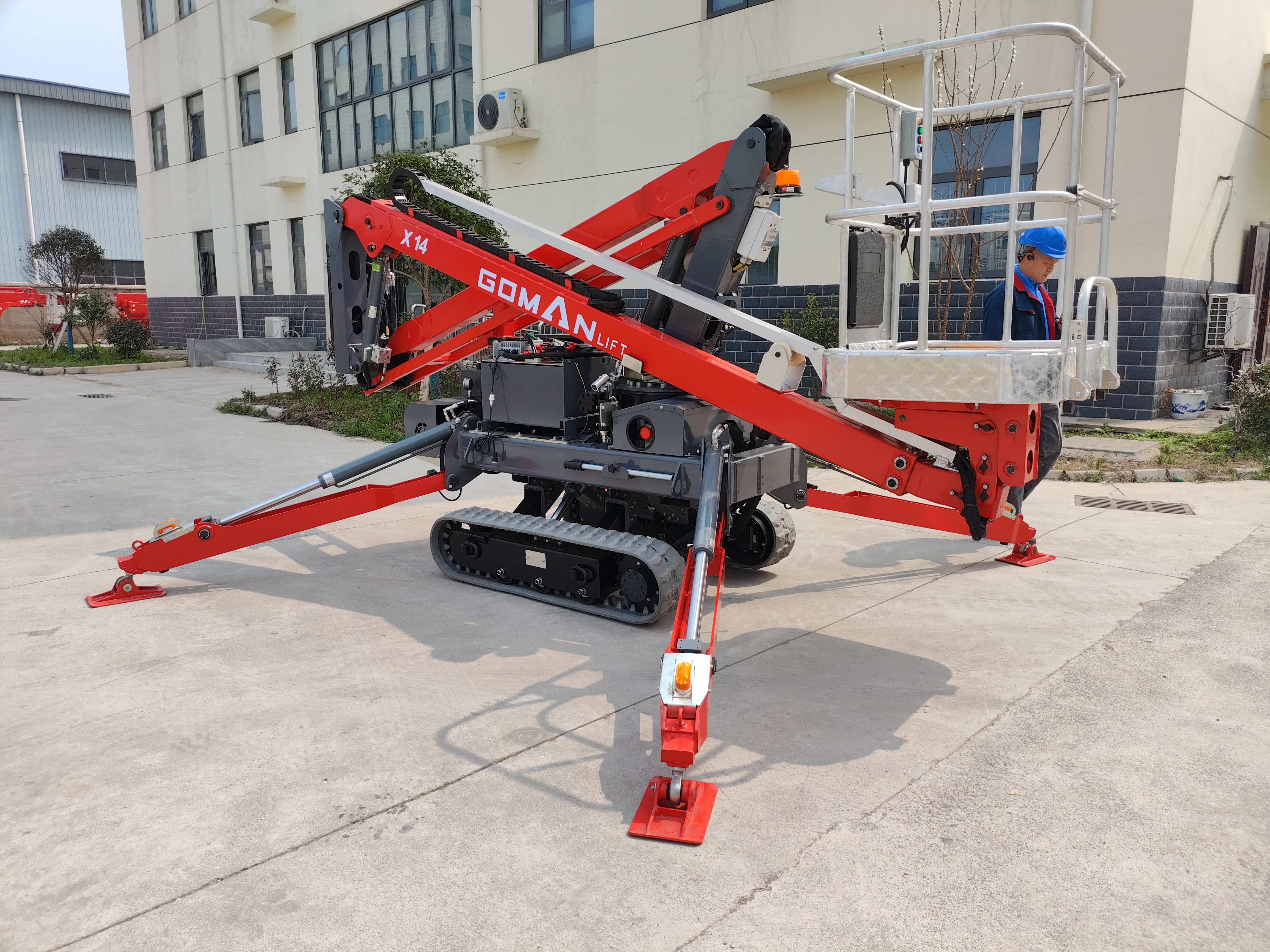
Operating heavy machinery indoors introduces severe air quality and safety regulations. Combustion engines running on diesel or gasoline cannot operate inside enclosed freight elevators. The confined space allows carbon monoxide to accumulate rapidly, creating lethal conditions in seconds. OSHA and EPA regulations strictly prohibit the use of internal combustion engines in unventilated indoor spaces.
This is where a hybrid spider lift becomes essential. Hybrid models feature dual power systems. They utilize a combustion engine for exterior travel, loading ramps, and rough terrain navigation. Once the machine reaches the building entrance, the operator switches to electric power. This seamless transition relies on either a plug-in AC electric motor or an onboard battery bank. Electric power provides safe, zero-emission loading and transport inside the elevator cab.
Selecting an electric power source involves significant weight implications. Traditional heavy lead-acid batteries provide reliable power but add massive weight to the machine chassis. A standard deep-cycle lead-acid battery bank can add 400 to 600 pounds to the total machine weight. This excess weight easily pushes the lift over a freight elevator's capacity limit.
Lightweight lithium-ion systems offer a modern alternative. Lithium-ion batteries provide higher energy density, faster charging times, and weigh significantly less than their lead-acid counterparts. Upgrading to a lithium-ion system shaves hundreds of pounds off the machine's gross weight. When every pound matters for elevator compliance, lithium-ion configurations are superior.
Battery Type | Average Weight Impact | Charge Speed | Maintenance Requirements |
|---|---|---|---|
Lead-Acid (Deep Cycle) | +400 to 600 lbs | 8 - 10 Hours | High (Watering, terminal cleaning) |
Lithium-Ion | +100 to 150 lbs | 2 - 4 Hours | Zero (Integrated Battery Management System) |
Before you reach the elevator doors, you must address the transport logistics of getting the machine to the site. Tracked machines require heavy-duty equipment trailers. You must factor in trailer weight capacities and tow vehicle ratings. Depending on the combined gross vehicle weight rating (CGVWR) of the truck, trailer, and lift, your drivers may require a Commercial Driver's License (CDL) for legal transport.
Navigating exterior bottlenecks presents the next hurdle. Survey the route from the unloading zone to the interior lobby. Standard perimeter gates, narrow service alleys, and steep loading docks block access frequently. Measure all exterior gates and walkways. Ensure the ground conditions can support the machine's weight before it reaches the building's threshold. Soft landscaping or hollow utility vaults will collapse under the point load of the tracks.
Finished lobbies leading to the elevator feature expensive flooring materials. Marble, polished concrete, and decorative tile are highly susceptible to point load cracking and surface scuffing. You must identify the risks of floor damage before tracking the machine indoors.
Implement strict mitigation tactics. Specify non-marking white rubber tracks for the machine to prevent black streaks on polished floors. Lay down rigid floor protection. A common field practice involves laying a base layer of 1/8-inch Masonite taped at the seams to prevent scratching, topped with 3/4-inch CDX plywood to distribute the machine's weight. Manage the break-over angle when crossing the elevator threshold. When a 4,000-pound machine rolls onto the elevator floor, the cab often drops slightly before the leveling sensors compensate. This creates a dangerous lip. Use heavy-duty steel transition ramps to bridge this gap smoothly. This prevents the machine from high-centering and stops the tracks from tearing the elevator door tracks out of the floor.
Loading a machine into an elevator requires strict protocols. Operators must never ride inside the elevator cab with the machine if clearances are tight. The risk of being trapped, pinned, or crushed against the cab walls is too high. Operators must use remote controls from outside the elevator cab. Walk the machine in slowly while standing in the lobby.
Utilize slow-speed tracking modes during the loading phase. Most machines feature a micro-speed or turtle mode that drastically reduces hydraulic flow to the drive motors. This allows for millimeter-precise movements. Keep the remote control tether clear of the tracks. A common mistake is allowing the tether cable to drag on the floor, where the tracks run it over and sever the connection, instantly disabling the machine halfway inside the elevator.
You must plan for the worst-case scenario: a mechanical or electrical failure while the lift is inside or partially inside the elevator. If a hydraulic hose bursts or a battery dies while the machine straddles the elevator threshold, you cannot simply push it out of the way. The building's freight elevator is now disabled, and the lobby is blocked.
Locate the hydraulic manifold on the machine chassis.
Open the drive bypass valves using the manual override tool. This disengages the hydraulic parking brakes on the track motors.
Attach heavy-duty manual come-alongs or winches to the designated chassis tie-down points.
Anchor the winches to structural pillars in the lobby and manually pull the dead machine out of the elevator doorway.
Close the bypass valves immediately to re-engage the brakes and secure the machine.
Selecting the right machine requires balancing the required working height against the exponential increase in machine weight. A machine that reaches 50 feet weighs significantly less than a machine that reaches 75 feet. You must establish a decision matrix based on your facility's specific limitations.
Target Working Height | Estimated Stowed Weight | Elevator Class Requirement | Ideal Application |
|---|---|---|---|
40 - 50 Feet | 3,000 - 4,500 lbs | Class A / Class B (Verify Limits) | Standard atriums, low-vaulted ceilings, light maintenance. |
55 - 65 Feet | 5,000 - 6,500 lbs | Class B / Class C1 | Mid-rise interior window washing, HVAC duct installation. |
70 - 85+ Feet | 7,000 - 9,000+ lbs | Class C1 / Class C2 Strictly Required | High-bay stadium lighting, large-scale commercial construction. |
Maximizing reach often requires sacrificing elevator compatibility. You cannot cheat physics. If your elevator is rated for 5,000 pounds, you cannot use an 8,000-pound machine, regardless of how badly you need the 80-foot reach. Buyers and rental managers must find the precise sweet spot for their facility, matching the maximum allowable elevator weight with the highest possible boom reach.
When you hover right at the elevator's weight limit, shedding a few hundred pounds makes the difference between success and failure. Evaluate models that allow for the quick removal of heavy components. Detaching the aluminum or fiberglass personnel basket removes 50 to 100 pounds. Removing the heavy steel outrigger pads saves another 50 pounds.
Some advanced models feature modular power packs. You can physically detach the auxiliary power unit or the combustion engine module from the chassis. You load these components into the elevator on a separate trip. This modular design strategy shaves off critical pounds, allowing a larger machine to meet strict elevator weight limits safely.
Consult your building’s structural engineer or elevator maintenance contractor to verify exact static and rolling load limits before selecting a machine.
Measure every doorway, hallway, and elevator cab physically instead of relying on outdated architectural blueprints.
Calculate the exact point load pressure of the machine to determine if you need steel distribution plates for the cab floor.
Specify a lithium-ion battery system or plug-in electric model for all indoor elevator transport to eliminate emissions and reduce gross weight.
A: Most narrow access models are engineered to collapse down to a width of 31 to 35 inches when fully stowed. This compact footprint allows the machine to easily pass through standard 36-inch single commercial doors and standard freight elevator doors without requiring structural modifications to the building.
A: The weight varies drastically based on the maximum working height. Smaller models reaching 40 to 50 feet typically weigh between 3,000 and 4,500 pounds. Larger models capable of reaching 75 to 85 feet can weigh between 7,000 and over 8,000 pounds. You must verify these weights against your elevator capacity.
A: No. Operating a diesel or gasoline engine inside an enclosed freight elevator is strictly prohibited. It violates OSHA and EPA regulations and creates an immediate, lethal carbon monoxide hazard. You must use plug-in electric or battery-powered modes for indoor transport.
A: Passenger elevators are designed for distributed human weight. Freight elevators feature reinforced structural frames. Specifically, Class C freight elevators are engineered to handle concentrated rolling loads from heavy machinery and forklifts, preventing the floor from shearing under the intense point pressure of steel tracks.
A: You calculate point load by taking the total operating weight of the machine and dividing it by the total surface area of the rubber tracks that are in direct contact with the floor. This provides the pounds per square inch (PSI) pressure exerted on the elevator cab floor.
