


No.188 Doubu Avenue, Hannan District, 430090 Wuhan, China


Views: 0 Author: Site Editor Publish Time: 2026-09-30 Origin: Site


Equipment arriving on-site only to be blocked by a single doorway or narrow gate results in immediate project delays and wasted rental fees. Crews stand idle while site supervisors scramble to find alternative access routes or dismantle architectural features. Facility managers and contractors must balance high-reach requirements, often exceeding 50 to 100 feet, with severe horizontal access constraints. This operational challenge requires precise alignment between existing architectural dimensions and specific equipment specifications.
Relying on a visual estimation of a doorway guarantees failure. Navigating complex indoor environments, historic buildings, or tight residential side yards demands a rigorous approach to spatial measurement. This guide establishes a technical framework for evaluating access points, understanding machine configurations, and specifying the correct narrow access spider lift based on verifiable clearance data rather than generalized marketing claims.
Standard Clearances: Most compact spider lifts are engineered to navigate standard 36-inch single commercial doors, with specialized models capable of passing through 32-inch ADA-compliant frames.
The Height Factor: Width is only half the equation; machines must also clear standard 80-inch commercial door heights while in their stowed transport configuration.
Configuration Requirements: Achieving minimum width often requires on-site machine adjustments, including track retraction and physical removal of the operator basket.
Measurement Realities: "Door width" must be calculated as the clear opening width at a 90-degree angle, accounting for hinges, panic hardware, and door stops, rather than the raw frame-to-frame measurement.
Power and Surface Compliance: Passing through a door is only the first step; indoor operation dictates the need for a hybrid spider lift (electric/lithium) and non-marking tracks to prevent floor damage and toxic emissions.
Defining exact dimensional thresholds prevents structural modifications to the facility. You want to bring heavy machinery deep into a building without removing door frames or damaging existing finishes. Equipment manufacturers design these machines specifically around common architectural standards, but field realities often differ from blueprints.
Door Type | Minimum Clear Opening | Target Machine Stowed Width | Required Tolerance |
|---|---|---|---|
ADA Residential / Historic | 32 inches | 29 - 30 inches | 1 - 2 inches |
Standard Commercial Single | 36 inches | 33 - 34 inches | 1 - 2 inches |
Oversized Commercial Single | 42 inches | 39 - 40 inches | 1 - 2 inches |
Standard Double Doors | 72 inches | 60+ inches | Ample |
The vast majority of mid-reach lifts are optimized specifically for standard commercial single doors, which typically measure 36 to 38 inches in width. Engineers design the stowed chassis of these machines to measure between 33 and 34 inches wide. This intentional sizing allows the equipment to pass through standard commercial entryways, service corridors, and freight elevators.
Sliding a 34-inch machine through a 36-inch opening leaves zero room for error. Safe passage requires strict tolerances. Operators need a minimum of one to two inches of clearance on each side to prevent catastrophic damage to the door frame, the surrounding drywall, or the machine itself. Navigating these tight tolerances often requires laying down track mats to prevent lateral sliding and using a spotter to guide the chassis through the threshold millimeter by millimeter. You must also account for kick plates and weather stripping that can reduce the usable width at the floor level.
Certain access routes present even stricter limitations. Historic buildings, residential side gates, and interior office partitions often feature narrower openings. To address this, manufacturers produce ultra-compact models designed to pass through facilities built to the ADA-mandated minimum clear opening width of 32 inches. These specialized machines can retract their tracks to achieve a stowed width of just 29 to 31 inches.
Achieving this ultra-narrow profile involves an inherent trade-off between chassis width and maximum vertical reach capabilities. A narrower wheelbase inherently limits the size and weight of the boom structure it can safely support. While these ultra-compact machines excel at navigating 32-inch doors, they generally top out at lower working heights compared to their slightly wider counterparts. Selecting these models requires confirming that the reduced reach is still sufficient for the intended overhead tasks.
Historically, achieving working heights above 75 feet required heavy, wide equipment. Larger lifts inherently demanded 48-inch to 60-inch double-door clearances, restricting their use in many indoor atriums or enclosed courtyards. If a facility only had single-door access, reaching high vaulted ceilings was nearly impossible without erecting massive, time-consuming scaffolding systems. Furthermore, many double doors feature a fixed center mullion that crews must unbolt and remove before a wide machine can pass.
Modern engineering advancements have fundamentally changed this dynamic. Select 30-meter lifts are now designed with highly complex boom geometries. These advanced machines fold compactly enough to pass through standard 36-inch single doors. By utilizing multi-telescopic booms and high-tensile steel, manufacturers have decoupled extreme vertical reach from the necessity of double-door access, opening up new possibilities for high-level maintenance in restricted facilities.
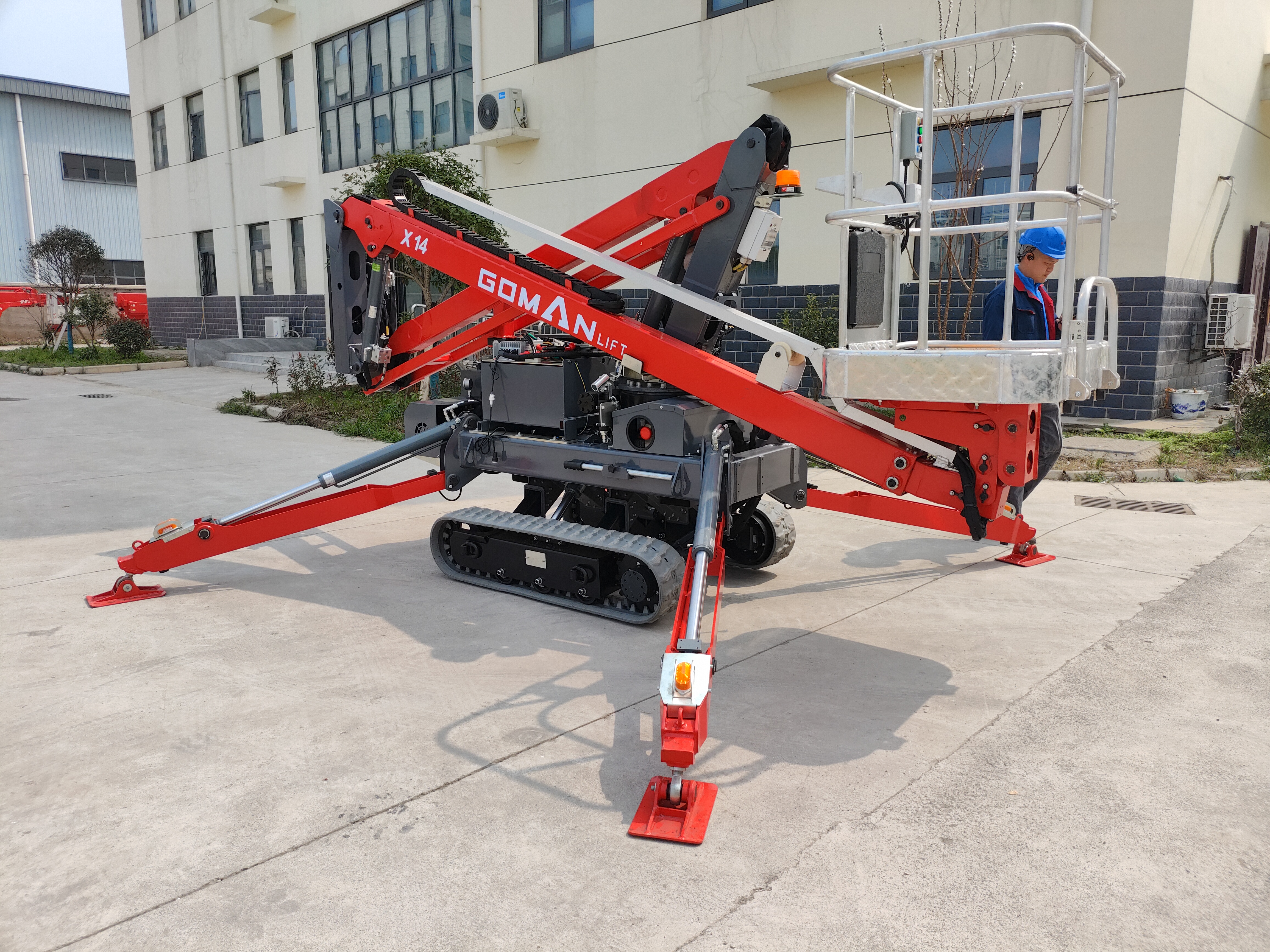
A lift does not arrive on-site ready to drive through a narrow doorway. The machine must be mechanically reconfigured from its operational state into its transport mode. Understanding the mechanical features that allow these machines to compress their footprint is critical for planning the logistics of site entry.
The undercarriage of a tracked spider lift is highly dynamic. To provide stability during operation, the tracks expand outward, creating a wide, stable base. To navigate tight gates and narrow corridors, the machine utilizes hydraulically adjustable undercarriages to narrow its stance.
With the push of a lever or the press of a button on the remote control, the hydraulic cylinders pull the track assemblies inward toward the central chassis. This retraction can reduce the overall width of the machine by several inches. Once the machine has successfully navigated the narrow access point and reached the work area, the operator expands the tracks back to their maximum width before deploying the outriggers and elevating the boom. Driving with retracted tracks raises the center of gravity, so operators must avoid side-slopes during transit.
The multi-position outriggers are the defining feature of this equipment class. When deployed, they spread out to create a massive stabilization footprint. When stowed for transport, their geometry is carefully engineered to minimize horizontal width.
Depending on the specific model, outriggers either fold vertically alongside the boom or tuck tightly underneath the chassis. The joints and hydraulic cylinders are designed to interlock closely with the main body of the lift. Operators must ensure that all four outriggers are fully retracted and locked into their designated transport positions. Micro-switches monitor these positions. Even a slightly misaligned outrigger pad can add an inch of width, causing the machine to catch on a door frame during transit.
The operator platform is often the widest fixed component on the machine. Standard baskets typically measure between 48 and 56 inches wide, making it physically impossible to drive the fully assembled machine through a 36-inch door. Detaching the operator platform is an absolute operational necessity to navigate tight corners and narrow thresholds.
Manufacturers design these baskets with quick-disconnect systems. The process involves pulling locking pins, disconnecting the quick-release hydraulic or electrical lines, and physically lifting the aluminum basket off its mounting bracket. Crews must account for the physical space needed to store the basket while the chassis drives through the door. The basket often weighs over 100 pounds, requiring two workers to manually carry it through the doorway and securely reassemble it on the other side before work can begin.
Measuring the width of a door frame with a tape measure is insufficient for guaranteeing access. Moving beyond simple width to a comprehensive 3D spatial assessment of the entire access route prevents costly equipment blockages. A proper site evaluation requires analyzing the entire path of travel from the unloading zone to the final work area.
Measuring wall-to-wall or frame-to-frame is a critical error that routinely causes access failures. The architectural frame width does not represent the actual usable space. You must calculate door width strictly as the clear opening width.
To determine the clear opening width, open the door to exactly 90 degrees. Measure the distance from the face of the door itself to the opposite door stop. You must account for the thickness of the door, protruding hinges, door closers, and crash bars. A standard 36-inch commercial door equipped with heavy-duty hinges and a panic bar may only provide 33 inches of actual clear opening width. If the selected machine is 34 inches wide, it will not fit without physically removing the door from its hinges and temporarily uninstalling the hardware.
Width is only one dimension; height is equally restrictive. Facility managers must evaluate the stowed height of the machine against the standard 80-inch commercial door height.
When a lift is fully stowed, the highest point of the machine—often the folded boom knuckle, the top of the hydraulic cylinder, or the upper track assembly—must clear the door header. If a machine measures 78.5 inches in height, it leaves a mere 1.5 inches of clearance. Any slight incline leading up to the door, or a raised threshold plate, can elevate the machine just enough to clip the door header, causing severe structural damage to the facility and the equipment.
Getting through the door is useless if the machine cannot navigate the hallway immediately behind it. Evaluators must assess the machine's overall length and turning geometry against standard 36-inch hallway minimums.
A lift may easily fit through the exterior door, but if it faces an immediate 90-degree turn in a narrow corridor, the length of the stowed boom may swing out and strike the opposing wall. This is known as boom sweep. Tracked machines can counter-rotate and spin in place, but the physical length of the chassis still requires a specific minimum turning radius. Mapping the exact dimensions of every corner, hallway intersection, and elevator lobby along the travel path is mandatory.
Assessing the vertical transition is often overlooked during site evaluations. Door sills, concrete steps, and ramp gradients directly impact the undercarriage clearance of a tracked machine.
When a machine drives up a steep ramp and transitions onto a flat floor, the tracks crest the peak of the incline. If the break-over angle is too sharp, the center of the machine's undercarriage will bottom out on the threshold, leaving the tracks spinning in the air. Navigating steep transitions often requires building custom ramp extensions using heavy-duty plywood or aluminum dock boards to shallow out the angle and prevent the machine from getting high-centered.
Selecting the right equipment requires balancing the strict need to fit through a door with the primary objective of actually reaching the work area. A machine that fits perfectly through the access point but falls ten feet short of the ceiling light fixture is entirely useless. Understanding the structural trade-offs helps in making the correct specification.
The physics of stability dictate equipment capabilities. A compact spider lift engineered to squeeze through a 32-inch door has a very narrow center of gravity when stowed. While the outriggers provide a wide base once deployed, the narrow chassis itself imposes limitations on the size and weight of the boom it can carry.
Ultra-narrow machines may have strict limitations on lateral outreach compared to wider models, even if they achieve impressive vertical heights. Reaching straight up is mechanically simpler than reaching far out over an obstacle. If the job requires reaching out 40 feet horizontally over a fixed seating area in an auditorium, an ultra-narrow machine may not have the structural mass to prevent tipping, requiring contractors to find a wider machine and potentially remove double doors to gain access.
Evaluating the ground bearing pressure is a critical safety requirement. A machine that fits perfectly through the door must still be supported by the floor structure beneath it. Narrow machines concentrate a significant amount of weight into a very small footprint.
When driving, the weight is distributed across the surface area of the rubber tracks. When operating, the entire weight of the machine is transferred to the four small outrigger pads. A 4,000-pound machine can easily crack porcelain tile or punch through raised access flooring. Distributing this intense point load often requires placing large, thick outrigger cribbing pads beneath the machine's feet to spread the weight over a larger surface area.
Passing through a doorway often signifies a transition from an outdoor environment to an indoor environment. This transition immediately triggers a new set of environmental and facility compliance requirements. The machine must not only fit physically but also operate safely within an enclosed space.
Operating a diesel or gasoline engine inside a closed building is a severe safety hazard. Toxic exhaust fumes, specifically carbon monoxide, accumulate rapidly, violating indoor air quality regulations and strictly enforced OSHA standards.
This dictates the necessity of a hybrid spider lift. These machines feature dual power sources. The operator uses the combustion engine to drive the machine across the outdoor parking lot and up to the doorway. Once at the threshold, the operator shuts down the engine and switches to the electric motor, powered either by an onboard lithium-ion battery pack or a direct plug-in extension cord. This allows the machine to drive indoors, deploy outriggers, and complete all high-reach tasks with zero emissions and minimal noise pollution.
Standard black rubber tracks leave deep, permanent scuff marks on hard surfaces. The friction generated when a tracked machine turns can destroy expensive interior finishes. Protecting interior assets such as polished terrazzo, marble lobbies, or hardwood gymnasium floors is paramount.
Indoor-compliant machines are equipped with specialized non-marking tracks. These tracks are manufactured from a unique rubber compound, typically gray or white, that lacks carbon black. Even with non-marking tracks, operators must exercise extreme caution. Turning sharply on a finished floor can still cause mechanical damage or surface scratching from screws or debris caught in the track treads. Sweeping the travel path and laying down protective floor coverings remains a best practice.
Even with precise measurements, access plans frequently fail in the field due to overlooked environmental factors or operational mistakes. Identifying these common failure points allows crews to implement mitigation strategies before the equipment arrives on-site.
Failing to measure the entire vertical travel path is a common error. Evaluators often verify the 80-inch door header but ignore the ceiling immediately inside the door. Low-hanging HVAC ducts, exposed sprinkler systems, decorative lighting fixtures, or non-standard bulkheads often hang well below the 80-inch mark.
Mitigation requires walking the exact path the machine will take and measuring the lowest hanging obstacle. If a sprinkler head hangs at 76 inches, a 79-inch tall machine will shatter it, causing catastrophic water damage. Spotters must watch the top of the machine just as closely as they watch the sides during indoor transit.
Tracked machines rely on friction to steer. When navigating polished indoor surfaces like waxed concrete or smooth tile, the tracks can lose traction. Instead of turning, the machine may slide laterally, crashing into walls or door frames during tight maneuvers.
Mitigation strategies involve altering the surface friction. Crews should use heavy-duty plywood sheets or specialized high-friction track mats. Placing these mats over smooth floors gives the rubber tracks the grip they need to execute precise turns without slipping or damaging the underlying surface.
Driving a heavy machine through a doorway with less than an inch of clearance on either side is highly stressful. If an operator is standing in the basket or sitting on the machine, their line of sight is heavily restricted. They cannot see the tracks engaging the door frame.
The solution is utilizing wired or wireless remote controls. Modern equipment allows the operator to detach the control box and walk alongside the machine. This ensures the operator has continuous visual confirmation of clearances during doorway transit. They can stop the machine instantly if the tracks drift too close to the frame, preventing impact damage.
Conduct a physical site walk with a tape measure to document the exact clear opening width of every door and gate on the travel path.
Map all architectural hardware, overhead obstructions, and floor surface types to identify potential snag points before the equipment arrives.
Consult an equipment specialist to verify the exact stowed transport specifications and ground bearing pressure of the shortlisted lifts.
Develop a written access plan detailing where tracks will retract, where the basket will detach, and where floor protection will be deployed.
A: Yes, most compact models fold down to pass through standard 36-inch commercial single doors. Specialized ultra-compact units can even navigate 32-inch ADA-compliant frames.
A: Measure the clear opening width. Open the door to 90 degrees and measure the narrowest point. Subtract the space taken up by hinges, the door thickness, and any panic hardware.
A: Most units are engineered to clear standard commercial door heights of 80 inches (6 feet, 8 inches) when fully stowed for transport. Always check for low-hanging door closers.
A: Frequently, yes. The operator basket is often wider than the stowed chassis. Removing it is a standard, quick-disconnect procedure to reduce the overall width of the machine.
A: It depends on the machine's stowed length and the hallway's width. While the machine may fit through the door, its length requires a specific turning radius that you must verify against hallway dimensions.
A: Yes, provided they use non-marking rubber tracks to prevent scuffing. You must also operate them on electric or lithium-ion power to eliminate toxic exhaust emissions indoors.
